

Overview › Build it in Excel › Lesson 6
Alternating treatments, multielement, and changing criterion
These designs use the same chart you already know. Each needs one or two extra settings: connecting points across blank cells, giving each condition its own marker and a legend, or adding dashed criterion lines.
You will be able to
- Connect each condition’s points across blank cells in an alternating treatments or multielement graph, and give each condition a marker that can be told apart in black and white.
- Add a borderless legend inside the plot that lists only the conditions a reader needs.
- Add dashed criterion lines and criterion labels to a changing criterion graph.
Your graph doesn't need this lesson. Lesson 6 is for alternating treatments, multielement (functional analysis), and changing criterion graphs. The graph you chose, Reversal (ABAB), has none of these extra settings. Go on to Lesson 7: Export and place the figure. If you haven't yet, stack your tiers in Lesson 5: Multiple baseline graphs, then go on to Lesson 7: Export and place the figure. Building one of those graphs instead? Choose it in the Graph box above so every lesson shows its steps, or go straight to its section: alternating treatments, multielement, or changing criterion.
Lessons 3 and 4 already covered these steps for your graph. They walked you through each one with your practice data and pictures. This lesson collects the rules and checks that are specific to each design in one place, so you can check your work or build the next graph from your own data. Your section: Alternating treatments design. Your section: Multielement design (functional analysis). Your section: Changing criterion design.
Alternating treatments design
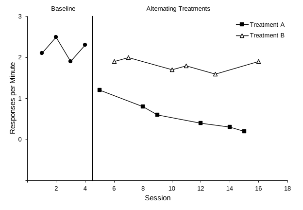
Practice data: practice-atd-data.xlsx, 16 sessions in A1:D17.
Give each condition its own column, just like a phase. During the alternating phase, each session's value goes in the column for the condition run that session. Each condition's column now has blank cells between its values.
| A | B | C | D | |
|---|---|---|---|---|
| 1 | Session | Baseline | Treatment A | Treatment B |
| 2–5 | 1–4 | 2.1 … 2.3 | ||
| 6 | 5 | 1.2 | ||
| 7 | 6 | 1.9 | ||
| 8 | 7 | 2.0 | ||
| 9 | 8 | 0.8 | ||
| 10 | 9 | 0.6 |
- Build the chart as usual. Select A1:D17 and insert a scatter chart with straight lines and markers, as in Lesson 2. Format it as in Lesson 3, with rate settings on the vertical axis: Minimum -1, Maximum 3, Major 1, horizontal axis crossing at -1, and format code 0;;0, so the labels are whole numbers. The practice rates peak at 2.5, so a maximum of 3 leaves room for the legend. Set the horizontal axis from 0 to 18, the first multiple of 2 past session 16, with a major unit of 2.
- Connect each condition across its blank cells. By default Excel leaves a gap at every blank, so each treatment would show as scattered points. Open Chart Design›Select Data. WindowsClick Hidden and Empty Cells at the bottom-left and choose Connect data points with line. Click OK twice. MacIn the Hidden and Empty Cells area at the bottom, set Show empty cells as to Connect data points with line. Click OK. The setting applies to every series in the chart. The baseline path still stops at the phase change, because its column has no later values to connect to.
- Give each condition a different marker. Click a condition's path, then open Format Data Series › Fill & Line › Marker. Under Marker Options, choose Built-in, a type, and size 6. The practice graph uses filled circles for Baseline, filled squares for Treatment A, and open triangles for Treatment B. For a filled marker, set Fill to Solid fill, black. For an open (hollow) marker, set Fill to Solid fill, white. Either way, set Border to Solid line, black, and keep every line black.
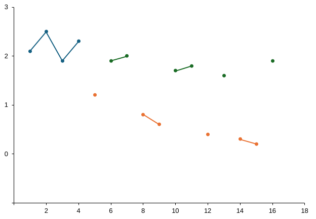
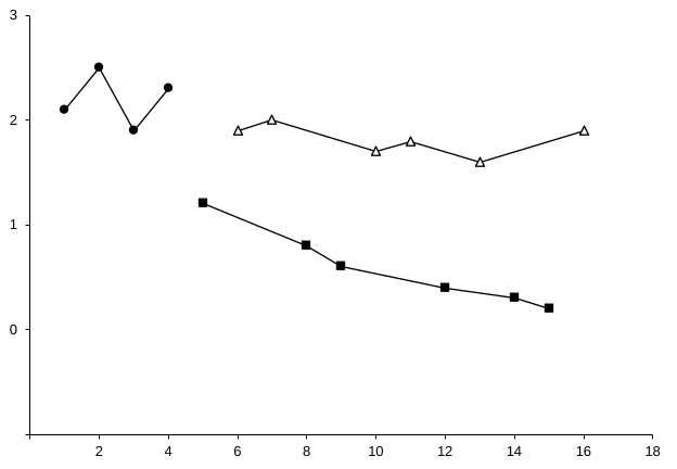
A path dips to zero between points? Excel connects only across cells that are truly empty. A cell that holds a space, text, or a formula that returns "" is plotted as 0. Select the cell and press Delete to empty it.
- Add the phase-change line and labels. Follow Lesson 4 exactly. The practice data change phase once, after session 4. The line table goes in F1:G3: Line X 4.5 in F2:F3, and Line Y -1 and 3 in G2:G3. Add it as one series named Phase change, with X values F2:F3 and Y values G2:G3. The label table goes in I1:K3: Baseline at Label X 2.5 and Alternating Treatments at 10.5, both with Label Y 3. Add it as a series named Phase labels, with X values J2:J3, Y values K2:K3, and Value From Cells I2:I3. Then turn off text wrapping for the labels, as Lesson 4 does: in Format Data Labels › Size & Properties › Alignment, uncheck Wrap text in shape. Otherwise Excel breaks Alternating Treatments onto two lines, and the second line hangs down into the plot. Then lower the top of the plot area about 0.2 in so both labels sit above it, and drag its right edge left about 0.1 in so it stays at least five-eighths as tall as it is wide (Lesson 4, Part B, step 7). Don’t lower the top much farther: a quarter inch leaves this plot area too flat.
- Add the legend last. Any series you add after the legend gets its own legend entry, so finish the lines and labels first. WindowsClick the chart, click + (Chart Elements), and check Legend. MacChoose Chart Design›Add Chart Element›Legend›Right. Double-click the legend to open Format Legend. Under Legend Options, uncheck Show the legend without overlapping the chart, so the plot area does not shrink to make room for it. Under Fill & Line › Border, choose No line. Drag the legend by its edge to an empty spot inside the plot area, such as the upper right, where it covers no data.
- Keep only the treatments in the legend. The legend lists every series, including Baseline, Phase change, and Phase labels. To remove one, click the legend once, click that entry once more so only it is selected, and press Delete. The series stays on the graph. The practice legend lists only Treatment A and Treatment B. Set the legend text to Arial 10 pt, black, like the other labels. Instead of a legend, you can also label each treatment's path directly with a text box near its last point.
Check your alternating treatments graph
- Treatment A and Treatment B are each one continuous path, connected across blank cells
- The Baseline path ends at session 4 and does not join either treatment
- Each condition has its own marker: filled circles (Baseline), filled squares (Treatment A), open triangles (Treatment B)
- One solid phase-change line at 4.5, from the horizontal axis to the top of the plot
- The labels Baseline and Alternating Treatments sit above the plot area, centered over their phases, each on one line
- A borderless legend inside the plot lists only Treatment A and Treatment B
- Vertical axis −1 to 3 in steps of 1, with whole-number labels and the −1 label hidden
Then read the graph. Do the two treatment paths separate clearly, with little or no overlap, across the whole alternating phase? See what experimental control looks like in an alternating treatments design.
Multielement design (functional analysis)
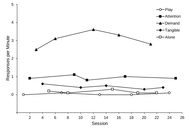
Practice data: practice-fa-data.xlsx, 25 sessions in A1:F26.
- One column per condition. Put session numbers in column A and one condition in each of columns B to F: Play, Attention, Demand, Tangible, and Alone. Type each session's rate under the condition run that session, so every row has exactly one rate. Type 0 for a session with no responding. Leave a cell blank only when that condition was not run in that session.
| A | B | C | D | E | F | |
|---|---|---|---|---|---|---|
| 1 | Session | Play | Attention | Demand | Tangible | Alone |
| 2 | 1 | 0 | ||||
| 3 | 2 | 0.9 | ||||
| 4 | 3 | 2.5 | ||||
| 5 | 4 | 0.6 | ||||
| 6 | 5 | 0.2 | ||||
| 7 | 6 | 3.1 | ||||
| 8 | 7 | 0.1 |
- Insert and format the chart. Select A1:F26, insert a scatter chart with straight lines and markers, and format it as in Lesson 3. On the vertical axis, set Minimum -1, Maximum 5, Major 1, horizontal axis crossing at -1, and format code 0;;0, so the labels are whole numbers. The practice rates peak at 3.6. A maximum of 5 leaves room for the legend in the upper right. Set the horizontal axis from 0 to 26, one more than the last session, with a major unit of 2.
- Connect each condition across its blank cells. Turn on Connect data points with line exactly as in step 2 of the alternating treatments design. Every condition's column has blanks between its values, so without this setting all five conditions show as scattered points.
- Use five distinguishable markers. The practice graph uses open circles for Play, filled squares for Attention, filled triangles for Demand, filled diamonds for Tangible, and open squares for Alone. Set each marker as in step 3 of the alternating treatments design, at size 6. Open circles for the control (Play) condition is a common pattern. What matters most is that every marker reads clearly in black and white and stays the same across all your figures.
- Skip the phase-change lines and phase labels. All five conditions alternate within one phase, so there is nothing to separate or name. The legend identifies the conditions instead.
- Add a legend inside the plot area. Add it, remove its border, and drag it into an empty part of the plot as in step 5 of the alternating treatments design. Set its text to Arial 10 pt, black. Keep all five conditions in the legend; this graph has no helper series to remove. The legend lists the series in column order. The practice file puts the control condition, Play, first. To change the order, move the columns before you insert the chart, or select a series in Select Data and use the Move Up and Move Down arrows. Whatever order you choose, use it in every figure.
Zero rates stay visible. With the floating zero from Lesson 3, sessions with no responding sit on the 0 line, just above the horizontal axis, instead of on it. Keep markers at size 6 or larger. When two conditions share a shape, as Attention and Alone do here, make one filled and the other open so they can still be told apart in black and white.
Check your multielement graph
- No phase-change lines and no phase labels
- Five paths, each connected across blank cells
- Five markers that can be told apart in black and white
- A borderless legend inside the plot lists Play, Attention, Demand, Tangible, and Alone
- Sessions with no responding are typed as 0 and sit on the 0 line, above the horizontal axis
- Vertical axis −1 to 5 in steps of 1, with whole-number labels and the −1 label hidden
Then read the graph. Is responding in any test condition consistently higher than in the Play (control) condition, with little overlap? See Functional analysis: differentiated or not?
In the practice graph, Demand is clearly highest, at 2.5 to 3.6 responses per minute. Attention (0.8 to 1.1) and, at a lower level, Tangible (0.3 to 0.6) are also above Play (0 to 0.1) in all five cycles, with no overlap. Alone stays low (0.1 to 0.3) and overlaps Play at 0.1. Because each test condition is compared with Play, not just with the highest condition, this graph suggests escape plus attention, and possibly tangible: multiple control worth following up.
Changing criterion design
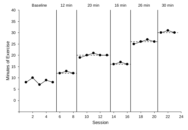
Practice data: practice-cc-data.xlsx, 23 sessions in A1:G24.
Why the subphases differ. The practice subphases last 3, 5, 3, 4, and 3 sessions, the criterion changes by different amounts (+8, −4, +10, and +4 minutes), and it steps back down from 20 to 16 minutes for a while. When behavior follows changes like these, time alone can’t explain them (see how the design shows control). The helper tables work the same for any subphase lengths and criteria: each criterion line spans exactly its own subphase.
- One column per subphase. Put Baseline, Phase 1, Phase 2, Phase 3, Phase 4, and Phase 5 in B1:G1, so the data path breaks at every criterion change. Select A1:G24, insert a scatter chart with straight lines and markers, and format it as in Lesson 3. On the vertical axis, set Minimum -5, Maximum 40, Major 5, horizontal axis crossing at -5, and format code 0;;0. The practice data peak at 31 minutes. A maximum of 40 keeps the highest point well below the top of the plot. Set the horizontal axis from 0 to 24, one more than the last session, with a major unit of 2.
- Add the phase-change lines. Follow Lesson 4. The practice data change phase after sessions 5, 8, 13, 16, and 20, so the line table in I1:J11 has five lines at 5.5, 8.5, 13.5, 16.5, and 20.5, each with Line Y -5 and 40. Add one series per line: I2:I3/J2:J3, I4:I5/J4:J5, I6:I7/J6:J7, I8:I9/J8:J9, and I10:I11/J10:J11. Keep these lines solid.
- Make a criterion-line table. Each criterion line is a two-point series. Its X values run from half a session before the subphase's first session to half a session after its last. Its Y values are the criterion twice. For a criterion of 12 during sessions 6–8: X = 5.5, 8.5 and Y = 12, 12. Type the table in P1:Q11.
| P | Q | ||
|---|---|---|---|
| 1 | Criterion X | Criterion Y | |
| 2 | 5.5 | 12 | ← 12 min, sessions 6–8 |
| 3 | 8.5 | 12 | |
| 4 | 8.5 | 20 | ← 20 min, sessions 9–13 |
| 5 | 13.5 | 20 | |
| 6 | 13.5 | 16 | ← 16 min, sessions 14–16 |
| 7 | 16.5 | 16 | |
| 8 | 16.5 | 26 | ← 26 min, sessions 17–20 |
| 9 | 20.5 | 26 | |
| 10 | 20.5 | 30 | ← 30 min, sessions 21–23 |
| 11 | 23.5 | 30 |
- Add each criterion line as a series. Use Chart Design›Select Data, then Add (Windows) or + (Mac), as you did for the phase-change lines. Name the first one Criterion, with X values P2:P3 and Y values Q2:Q3. Add four more the same way: P4:P5/Q4:Q5, P6:P7/Q6:Q7, P8:P9/Q8:Q9, and P10:P11/Q10:Q11.
- Make criterion lines dashed. Click a criterion line. In Format Data Series › Fill & Line › Line, choose Solid line, black, 1 pt, and a dashed Dash type such as Dash. Set Marker › Marker Options to None. Repeat for the other four. Dashing keeps the criterion visibly different from the data path and the solid phase-change lines.
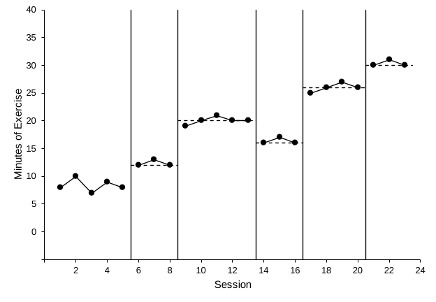
- Label each subphase with its criterion. Use the phase-label method from Lesson 4. The label table goes in L1:N7: Baseline at Label X 3, then 12 min at 7, 20 min at 11, 16 min at 15, 26 min at 18.5, and 30 min at 22, all with Label Y 40. Use X values M2:M7, Y values N2:N7, and Value From Cells L2:L7. Then lower the top of the plot area about 0.2 in so the labels sit above it, as in Lesson 4, Part B, step 7. Don’t go much farther: a quarter inch leaves this plot area less than five-eighths as tall as it is wide.
Changed a criterion? Edit its two Criterion Y cells in column Q and its label in column L. The dashed line and the label move with the numbers.
Check your changing criterion graph
- The data path breaks at every phase change
- Five solid phase-change lines at 5.5, 8.5, 13.5, 16.5, and 20.5, from the horizontal axis to the top of the plot
- Five dashed criterion lines at 12, 20, 16, 26, and 30, each spanning only its own subphase
- Phase-change lines and criterion lines have no markers
- The labels Baseline, 12 min, 20 min, 16 min, 26 min, and 30 min sit above the plot area, centered over their subphases
- Vertical axis −5 to 40 in steps of 5, with the −5 label hidden
Then read the graph. Does responding shift to each new criterion soon after it changes and stay near it until the next change? See what experimental control looks like in a changing criterion design.
All three designs are available as ready-made templates, with the gap settings, markers, legends, criterion lines, and labels already in place.